Why do I need ratios to design a voltage divider?
Two resistors in series split a voltage in proportion to their resistances. The output is the input times the bottom resistor's share of the total. That ratio is how circuits make 3.3 volts from 5, read a battery with a microcontroller, or set a sensor's range. A load on the output changes the ratio.
- Output voltage
- 6.91 V
- Current through the divider
- 2.09 mA
- Divider ratio
- ×0.767
Challenge: Make 3.3 V from your input (within 0.05 V).
More settings
Play
Change the two resistors. The output voltage slides between zero and the input.
Challenge: Make 3.3 V from your input (within 0.05 V). The box under the picture turns green when you get it.
Stuck? Pick one of the examples from the “Try an example” menu, or press “New example.”
Understand
The same current flows through and , so by Ohm's law each resistor drops voltage in proportion to its resistance. The output is the bottom resistor's share:
That fraction is a ratio: double both resistors and the output doesn't change. The bar on the right shows the share. Connect a load and it sits in parallel with , shrinking the share.
Use
Every input has a unit menu, so you can type values in the units you already have. Results follow your units.
Show the work
- Divider
V_{out} = 9 \times \frac{3300}{1000 + 3300} = 6.907\,\mathrm{V} - Current
I = \frac{9}{4300} = 0.002093\,\mathrm{A}
Export
Enter the input and the two resistors. Turn on "Connect a load" in "More settings" to see how an input or sensor on the output pulls it down.
- Standard resistor values (E12/E24) rarely hit the ratio exactly; check with the real values.
- Resistor tolerance (±1% or ±5%) shifts the output by a similar percent.
For learning and estimation. Verify with applicable codes, standards, and a qualified professional before using in design, construction, or safety-critical work.
Cheat card
| Symbol | Meaning | Unit |
|---|---|---|
| top resistor | Ω | |
| bottom resistor | Ω | |
| load on the output | Ω |
- Equal resistors give exactly half.
- Keep the load at least 10× bigger than R₂ or the output sags.
- Larger resistors waste less current but are more sensitive to loading.
Where it’s used
- Electrical & Electronics
Engineers use dividers to scale sensor and battery voltages into an analog-to-digital converter's range. - Hobbies & Crafts
Arduino and Raspberry Pi projects use a divider to shift 5 V signals down to 3.3 V.
Related exhibits
 Start here
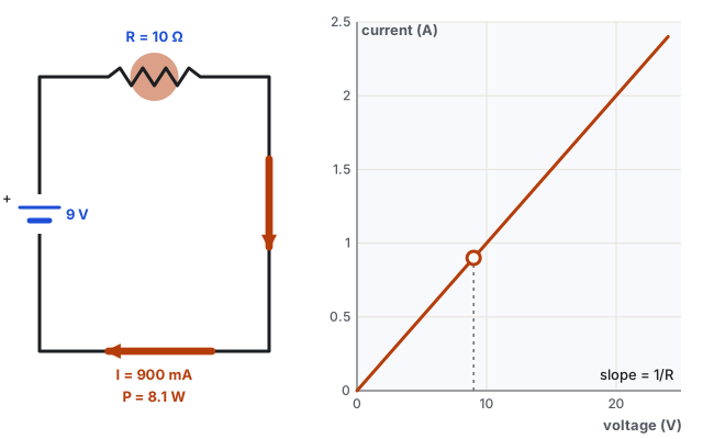
Ohm’s law: how much current flows?
Push harder (volts) or squeeze tighter (ohms), and watch the current change.
 Go further
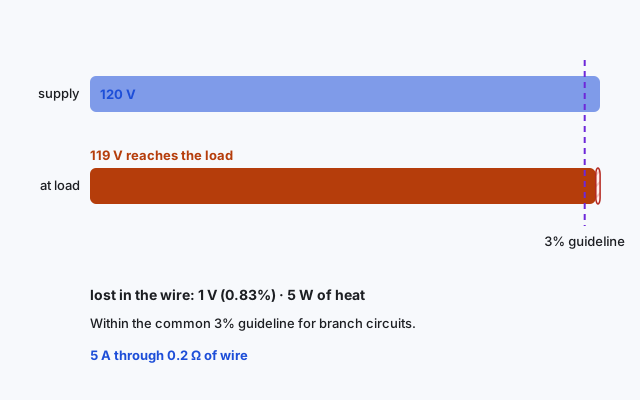
Voltage drop: what the wire takes before the load gets it
Current times wire resistance is voltage you never get to use.
 Also try
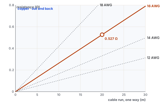
Wire resistance: longer and thinner resist more
Resistance grows with length and shrinks with thickness. Pick the wire that keeps it low.
Questions people ask
How does a voltage divider work?
The same current flows through both resistors, so each drops a share of the voltage proportional to its resistance. The output is the bottom share.
Why does the output drop when I connect something?
The load is in parallel with the bottom resistor, making it effectively smaller, which lowers its share of the voltage.
Can I use a voltage divider as a power supply?
Only for tiny currents. For anything that draws real current, use a voltage regulator.